Power Flow: Mvar Sharing between Generators
This is a subtopic of the Power Flow Solution Theory Help.
On the Simulator Options dialog under the Power Flow Solution, Advanced Options tab there is an option called Sharing of generator Vars across groups of buses during remote regulation. When several buses have generators that control the voltage at single bus, this option determines the method used to determine each bus' share of the Mvar support. There are three options as follows.
- OPTION#1: Allocate across buses using the user-specified remote regulation percentages. This option most closely matches the sharing seen in RAW files. The allocation of Mvars to a bus will be proportional to the average value of the RegFactor for all generators at the bus.
- OPTION #2: Allocate so all generators are at same relative point in their [min .. max] var range. This option most closely matches the sharing seen in a few EMS solutions PowerWorld has seen. The RegFactor values are not used with this option, but the MvarMax and MvarMin values will impact the allocation.
- OPTION #3: Allocate across buses using the SUM OF user-specified remote regulation percentages. This option most closely matches the sharing seen in EPC files. The allocation of Mvars to a bus will be proportional to the summation of the RegFactor for all generators at the bus.
In an Auxiliary file, this option is part of the object Sim_Solution_Options and can be changed by change the field named MvarSharingAllocation which can set to either RegPerc, MinMaxRange, or SumRegPerc.
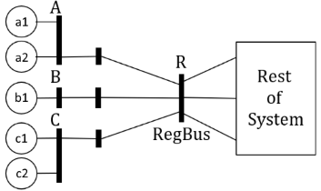
To demonstrate what these options mean consider the following system where there are 3 buses (A, B, and C) that have generators that are regulating a remote bus.
|
|
Bus A has 2 generators (a1 and a2), Bus B has one generator (b1), and Bus C has 2 generators (c1 and c2). The RegFactors and generator Mvar limits are as shown in the following table.
|
|
As an example assume that the summation of the Mvar from all 5 generators in a solution ends up being +180 Mvar. The relative Mvar outputs of the generators will be impacted by this option and will be described as follows.
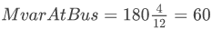
- OPTION #1 The first option means that the RegFactor is interpreted for each bus, and thus buses are assigned Mvar in proportion to the factors 2, 6, and 4. These factors are then normalized so that Bus A generators will provide 2/12 of the Mvars, Bus B will provide 6/12, and Bus C will provide 4/12. With a total of 180 Mvar that means Bus A provides 30 Mvar, Bus B provides 90 Mvar, and Bus C provides 60 Mvar. This then means that a1 and a2 provide 15 Mvar each, b1 provides 90 Mvar, and c1 and c2 provide 30 Mvar each.

- Thus for generator c2 its output will be
 , but then this is split by using the RegFactor at bus C so that c1 gets half of this which is 30 Mvar
- OPTION #2 The second option means that each generator will end up at the same relative point within its Min/Max Mvar range. The summation of minimum Mvars is -300 and the summation of maximum Mvar is +300. This gives a total range of 600 Mvar. The desired total of 180 Mvar, which is 480 Mvar above the minimum Mvar total. That means we want to be 480/600 and thus 80% of the way from the minimum to maximum value for each generator. Written in equation for each generator's output will then be set equal to

- Tthus for generator c2 its output will be

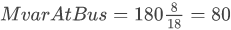
- OPTION #3 The third option means the RegFactor is interpreted for each bus as the summation of values assigned for each generator. This is the same as each individual generator providing Mvar in proportion to its own RegFactor. This means that generators a1 and a2 will each provide 2/18 of the Mvars, generator b1 will provide 6/18, and generators c1 and c2 will each provide 4/18. With a total of 180 Mvar this then means that a1 and a2 provide 20 Mvar each, b1 provides 60 Mvar, and c1 and c2 provide 40 Mvar each.

- Thus for generator c2 its output will be
 , but then this is split by using the RegFactor at bus C so that c1 gets half of this which is 40 Mvar
Generator Outputs if the summation of outputs is 180 Mvar
|
|
Generator |
RegFactor |
MvarMin |
MvarMax |
Option #1 Mvar |
Option #2 Mvar |
Option #3 Mvar |
|
a1 |
2.0 |
-60.0 |
+40.0 |
+15 |
+20 |
+20 |
|
|
a2 |
2.0 |
-50.0 |
+30.0 |
+15 |
+14 |
+20 |
|
|
b1 |
6.0 |
-100.0 |
+100.0 |
+90 |
+60 |
+60 |
|
|
c1 |
4.0 |
-50.0 |
+50.0 |
+30 |
+30 |
+40 |
|
|
c2 |
4.0 |
-40.0 |
+80.0 |
+30 |
+56 |
+40 |
PowerWorld Corporation has found that various software tools choose to do this Mvar allocation across generators in different ways. The three methods described here are the ones we have seen. Our recommendation would be to use the second option to keep generators within the same point of the MvarMin to MvarMax range as this has the advantage of not requiring the extra input parameter RegFactor and also means that all generators participating in remote regulation together will hit their limits at the same point. See discussion below which shows that hitting and backing off of generator limits using the other options can be quite complex.
One clarification when allocating with this recommended option however: it is possible for a solution to have a mixture of positive and negative Mvar outputs even when regulating together. As an example consider what happens when the summation of generator Mvar outputs is either 36.0 or 0.0 Mvar. The various options would yield those shown below where generators at Bus A are operating at a negative Mvar, while generators c2 is operating at a higher positive value. This is occurring because generators a1 and a2 have a larger negative Mvar range than positive, while generator c2 has a larger positive range than negative.
Generator Outputs if the summation of outputs is 36.0 or 0.0 Mvar
|
|
Mvar Outputs for total of 36.0 |
Mvar Outputs for total of 0.0 |
||||||||||
|
Generator |
RegFactor |
MvarMin |
MvarMax |
Option #1 Mvar |
Option #2 Mvar |
Option #3 Mvar |
Option #1 Mvar |
Option #2 Mvar |
Option #3 Mvar |
|||
|
a1 |
2.0 |
-60.0 |
+40.0 |
+3 |
-4.0 |
+4 |
0 |
-10 |
0 |
|||
|
a2 |
2.0 |
-50.0 |
+30.0 |
+3 |
-5.2 |
+4 |
0 |
-10 |
0 |
|||
|
b1 |
6.0 |
-100.0 |
+100.0 |
+18 |
+12.0 |
+12 |
0 |
0 |
0 |
|||
|
c1 |
4.0 |
-50.0 |
+50.0 |
+6 |
+6.0 |
+8 |
0 |
0 |
0 |
|||
|
c2 |
4.0 |
-40.0 |
+80.0 |
+6 |
+27.2 |
+8 |
0 |
+20 |
0 |
|||
Enforcement of Generator Mvar Limits
When using the OPTION#2 (MinMaxRange), the hitting of minimum and maximum Mvar limits for the generators occurs simultaneously across all generators performing control together. This is the most straighforward of the options to understand.
For OPTION #1 and OPTION #3 however as you increase the total Mvar from all 5 generators then you will encounter solutions where within a group of generators regulating the same bus there is a mixture of generators at a limit and generators not at a Mvar limit. In PowerWorld Simulator we allocate the Mvars to buses using the algorithms described first. If the summation of Mvar limits of generators at a bus can handle the Mvar allocated to the bus then the Mvars will stay at that bus and be spread around ensuring no generator is outside its Mvar limits. This is done before pushing those Mvars to other buses in the remote regulation group.
As an example, consider OPTION#1 in the previous system and what occurs if a total of 250 Mvar is spread across these generators. Initially, internally we would assign values of 20.833 Mvar to a1 and a2, 125.000 to b1, and 41.667 to c1 and c2. However, this would result in b1 exceeding its MvarMax limit of 100. Therefore we would allocate the 25 extra Mvar by renormalizing the Mvar allocation for the remaining generators at A and C and we would end up with the entries shown in the final column on the right below.
Generator Outputs if the summation of outputs is 250 Mvar
|
|
Generator |
RegFactor |
MvarMin |
MvarMax |
Option #1 Mvar |
Move Mvars to Bus A and C |
Option #1 Mvar FINAL |
|
a1 |
2.0 |
-60.0 |
+40.0 |
+20.833 |
Add 4.167 |
+25 |
|
|
a2 |
2.0 |
-50.0 |
+30.0 |
+20.833 |
Add 4.167 |
+25 |
|
|
b1 |
6.0 |
-100.0 |
+100.0 |
+125.000 |
Set back to limit |
+100 |
|
|
c1 |
4.0 |
-50.0 |
+50.0 |
+41.667 |
Add 8.333 |
+50 |
|
|
c2 |
4.0 |
-40.0 |
+80.0 |
+41.667 |
Add 8.333 |
+50 |
Take this a step further and let's go to 288 Mvar output. Initially we get the generator b1 allocated to 144 Mvar which is beyond its limit. Because there is only one generator at bus B, we must move Mvars from Bus B over to Buses A and C and we get generators at bus A at 31.333 and generators at bus C at 62.667. At this point however, generators a2 and c1 are now violating their MvarMax limits. We do not reallocate those Mvars across the entire group though because both Bus A and C have other generators at their respective buses which can take on those Mvars. Thus the extra Mvars at generator c1 are moved to c2 and the extra Mvars at a2 are moved to a1.
Generator Outputs if the summation of outputs is 288 Mvar
|
|
Generator |
RegFactor |
MvarMin |
MvarMax |
Option #1 Mvar |
Move Mvars to Bus A and C |
Option #1 Mvar |
Shift at Bus Only |
Option #1 Mvar FINAL |
|
|
a1 |
2.0 |
-60.0 |
+40.0 |
+24 |
Add 7.333 |
+31.333 |
Reallocate at the Buses A and C to keep within limits |
+1.333 |
+32.667 |
|
|
a2 |
2.0 |
-50.0 |
+30.0 |
+24 |
Add 7.333 |
+31.333 |
-1.333 |
+30 |
||
|
b1 |
6.0 |
-100.0 |
+100.0 |
+144 |
Set back to limit |
+100 |
+100 |
|||
|
c1 |
4.0 |
-50.0 |
+50.0 |
+48 |
Add 14.667 |
+62.667 |
-12.667 |
+50 |
||
|
c2 |
4.0 |
-40.0 |
+80.0 |
+48 |
Add 14.667 |
+62.667 |
+12.667 |
+75.333 |
Finally as the most extreme example, consider the situation where 297 Mvar are needed. It proceeds along but in the second step the total allocated to Bus C becomes 131.333 which is above the summation of its MvarMax, so that then gets moved over to bus A.
Generator Outputs if the summation of outputs is 297 Mvar
|
|
Generator |
RegFactor |
MvarMin |
MvarMax |
Option #1 Mvar |
Move Mvars to Bus A and C |
Option #1 Mvar |
Shift at Bus Only |
Move C to A |
Option #1 Mvar FINAL |
|
|
a1 |
2.0 |
-60.0 |
+40.0 |
+24.75 |
Add 8.083 |
+32.833 |
Bus C now has 131.333 MW which is above the summation of its Max Mvar. Also generator a2 at bus |
+2.833 |
+1.333 |
+37 |
|
|
a2 |
2.0 |
-50.0 |
+30.0 |
+24.75 |
Add 8.083 |
+32.833 |
-2.833 |
+30 |
|||
|
b1 |
6.0 |
-100.0 |
+100.0 |
+148.5 |
Set back to limit |
+100 |
+100 |
||||
|
c1 |
4.0 |
-50.0 |
+50.0 |
+49.5 |
Add 16.167 |
+65.667 |
-15.667 |
+50 |
|||
|
c2 |
4.0 |
-40.0 |
+80.0 |
+49.5 |
Add 16.167 |
+65.667 |
+15.667 |
-1.333 |
+80 |